|
|
|
|
|
|
|
|
|
|
|
|
|
|
|
|
|
|
|
|
|
|
|
|
|
|
|
|
|
|
|
|
|
|
|
|
|
|
|
|
|
|
|
|
|
|
|
|
|
|
|
|
|
|
|
|
|
|
|
|
|
|
|
|
|
|
|
|
|
|
|
|
|
|
|
|
|
|
|
|
|
|
|
|
|
|
|
|
|
|
|
|
|
|
|
|
|
|
|
|
|
|
|
|
|
|
|
|
|
|
|
|
|
|
|
|
|
|
|
|
|
|
|
|
|
|
|
|
|
|
|
|
|
|
|
|
|
|
|
|
|
|
|
|
|
|
|
|
|
|
|
|
|
|
|
|
|
|
|
|
|
|
|
|
|
|
|
|
|
|
|
|
|
|
|
|
|
|
|
|
|
|
|
|
|
|
|
|
|
|
|
|
|
|
|
|
|
|
|
|
|
|
|
|
|
|
|
|
|
|
|
|
|
|
|
|
|
|
|
|
|
|
|
|
|
|
|
|
|
|
|
|
|
|
|
|
|
|
|
|
|
|
|
|
|
|
|
|
|
|
|
|
|
|
|
|
|
|
|
|
|
|
|
|
|
|
|
|
|
|
|
|
|
|
|
|
|
|
|
|
|
|
|
|
|
|
|
|
|
|
|
|
|
|
|
|
|
|
|
|
|
|
|
|
|
|
|
|
|
|
|
|
|
|
|
|
|
|
|
|
|
|
|
|
|
|
|
|
|
|
|
|
|
|
|
|
|
|
|
|
|
|
|
|
|
|
|
|
|
|
|
|
|
|
|
|
|
|
|
|
|
|
|
|
|
|
|
|
|
|
|
|
|
|
|
|
|
|
|
|
|
|
|
|
|
|
|
|
|
|
|
|
|
|
|
|
|
|
|
|
|
|
|
|
|
|
|
|
|
|
|
|
|
|
|
|
|
|
|
|
|
|
|
|
|
|
|
|
|
|
|
|
|
|
|
|
|
|
|
|
|
|
|
|
|
|
|
|
|
|
|
|
|
|
|
|
|
|
|
|
|
|
|
|
|
|
|
|
|
|
|
|
|
|
|
|
|
|
|
|
|
|
|
|
|
|
|
| ANSI
B16.36 FORGED FLANGES |
|
|
|
|
|
Unit: mm |
|
|
|
|
|
|
|
|
|
|
|
|
|
|
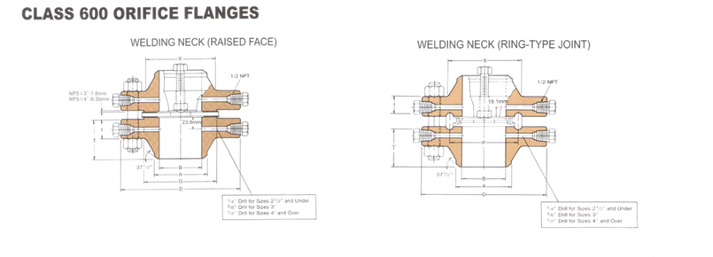
| Class
600 Orifice Flanges |
|
|
|
|
|
|
|
|
|
|
|
|
|
|
|
|
|
|
|
|
|
|
| Nominal
Pipe Size |
Outside Diam of Flange |
Thickness
of Flange (1) |
Diam of Hub at base |
Diam of raised face |
Diam of Hub Bevel |
Length
thru Hub (1) |
Bore
(B) |
Pitch Diam of Ring and
Groove |
Ring Number |
Depth
of jack screw slot |
jack
screw size |
Drilling
Template |
Nominal Pipe Size |
| Raised Face |
Ring
Joint |
Welding
Neck |
Slip-
on & threaded |
Welding
Neck |
Slip-
on |
Raised
face |
Ring
Joint |
Raised
face (inch) |
Ring
Joint (inch) |
Diam of
bolt circle |
Number
of Bolts |
Diam. Of
Stud Bolts (inch) |
Diam.
Of stud Bolt Holes |
Length
of stud bolts |
| D |
X |
G |
A |
Raised
Face |
Ring
joint |
Raised
Face |
Ring
joint |
P |
RF |
RTJ |
Raised
face |
Ring
Joint |
| 1 |
124 |
38.1 |
31.8 |
53.8 |
50.8 |
33.5 |
82.6 |
76.2 |
47.8 |
41.1 |
See Note (1) to be specified by purchaser |
34.5 |
50.8 |
R16 |
9.7 |
6.4 |
5/8×4.00 |
5/8×4.75 |
88.9 |
4 |
5/8 |
17.5 |
19.1 |
127.0 |
146.1 |
1 |
| 1 ¼ |
133 |
38.1 |
31.8 |
63.5 |
63.5 |
42.2 |
84.1 |
77.7 |
46.0 |
39.6 |
43.2 |
60.3 |
R18 |
9.7 |
6.4 |
5/8×4.00 |
5/8×4.75 |
98.6 |
4 |
5/8 |
17.5 |
- |
127.0 |
120.7 |
1 ¼ |
| 1 ½ |
155 |
38.1 |
31.8 |
69.9 |
73.2 |
48.3 |
85.9 |
79.2 |
47.8 |
41.1 |
49.5 |
68.3 |
R20 |
12.7 |
6.4 |
¾×4.25 |
¾×5.00 |
114.3 |
4 |
¾ |
20.6 |
22.4 |
133.4 |
152.4 |
1 ½ |
| 2 |
165 |
38.1 |
31.8 |
84.1 |
91.9 |
60.5 |
85.9 |
79.2 |
49.3 |
42.9 |
62.0 |
82.6 |
R23 |
9.7 |
6.4 |
5/8×4.00 |
5/8×4.75 |
127.0 |
8 |
5/8 |
17.5 |
19.7 |
127.0 |
152.4 |
2 |
| 2 ½ |
191 |
38.1 |
31.8 |
100.1 |
104.6 |
73.2 |
88.9 |
82.6 |
50.8 |
44.5 |
74.7 |
101.6 |
R26 |
12.7 |
6.4 |
¾×4.25 |
¾×5.00 |
149.4 |
8 |
¾ |
20.6 |
22.4 |
133.4 |
158.8 |
2 ½ |
| 3 |
210 |
38.1 |
31.8 |
117.3 |
127.0 |
88.9 |
88.9 |
82.6 |
52.3 |
46.0 |
90.7 |
123.8 |
R31 |
12.7 |
6.4 |
¾×4.25 |
¾×5.00 |
168.1 |
8 |
¾ |
20.6 |
22.4 |
133.4 |
158.8 |
3 |
| 4 |
273 |
38.1 |
38.1 |
152.4 |
157.2 |
114.3 |
101.6 |
101.6 |
53.8 |
53.8 |
116.1 |
149.2 |
R37 |
6.4 |
15.7 |
¾×3.00 |
¾×4.00 |
215.9 |
8 |
7/8 |
25.4 |
25.4 |
152.4 |
165.1 |
4 |
| 5 |
330 |
44.5 |
44.5 |
189.0 |
185.7 |
141.2 |
114.3 |
114.3 |
60.5 |
60.5 |
143.8 |
181.0 |
R41 |
6.4 |
15.7 |
¾×3.50 |
¾×4.50 |
266.7 |
8 |
1 |
28.4 |
28.4 |
139.7 |
177.8 |
5 |
| 6 |
356 |
47.8 |
47.8 |
222.3 |
215.9 |
168.4 |
117.3 |
117.3 |
66.5 |
66.5 |
170.7 |
211.1 |
R45 |
12.7 |
22.4 |
1×3.50 |
1×4.50 |
292.1 |
12 |
1 |
28.4 |
28.4 |
177.8 |
190.5 |
6 |
| 8 |
419 |
55.6 |
55.6 |
273.1 |
269.7 |
219.2 |
133.4 |
133.4 |
76.2 |
76.2 |
221.5 |
269.9 |
R49 |
12.7 |
22.4 |
1×4.00 |
1×4.75 |
349.3 |
12 |
1 1/8 |
31.8 |
31.8 |
196.9 |
209.6 |
8 |
| 10 |
508 |
63.5 |
63.5 |
342.9 |
323.9 |
273.1 |
152.4 |
152.4 |
85.9 |
85.9 |
276.4 |
323.9 |
R53 |
12.7 |
22.4 |
1×4.00 |
1×5.00 |
431.8 |
16 |
1 ¼ |
35.1 |
35.1 |
222.3 |
235.0 |
10 |
| 12 |
559 |
66.5 |
66.5 |
400.1 |
381.0 |
323.9 |
155.4 |
155.4 |
91.9 |
91.9 |
327.2 |
381.0 |
R57 |
12.7 |
22.4 |
1×4.50 |
1×5.00 |
489.0 |
20 |
1 ¼ |
35.1 |
35.1 |
228.6 |
241.3 |
12 |
| 14 |
603 |
69.9 |
69.9 |
431.8 |
412.8 |
355.6 |
165.4 |
165.4 |
|
|
419.1 |
R61 |
12.7 |
22.4 |
1×5.00 |
1×5.50 |
527.1 |
20 |
1 3/8 |
38.1 |
38.1 |
241.3 |
254.0 |
14 |
| 16 |
686 |
76.2 |
76.2 |
495.3 |
469.9 |
406.4 |
177.8 |
177.8 |
|
469.9 |
R65 |
12.7 |
22.4 |
1×5.00 |
1×5.50 |
603.3 |
20 |
1 ½ |
41.1 |
41.1 |
260.4 |
273.1 |
16 |
| 18 |
743 |
82.6 |
82.6 |
546.1 |
533.4 |
457.2 |
184.2 |
184.2 |
|
533.4 |
R69 |
12.7 |
22.4 |
1×5.00 |
1×5.75 |
654.1 |
20 |
1 5/8 |
44.5 |
44.5 |
297.4 |
292.1 |
18 |
| 20 |
813 |
88.9 |
88.9 |
609.6 |
584.2 |
508.0 |
190.5 |
190.5 |
|
584.2 |
R73 |
12.7 |
22.4 |
1×6.00 |
1×6.25 |
723.9 |
24 |
1 5/8 |
44.5 |
44.5 |
298.5 |
317.5 |
20 |
| 24 |
940 |
101.6 |
101.6 |
717.6 |
692.2 |
609.6 |
203.2 |
203.2 |
|
692.2 |
R77 |
12.7 |
22.4 |
1×6.00 |
1×7.00 |
838.2 |
24 |
1 7/8 |
50.8 |
50.8 |
336.6 |
342.9 |
24 |
| Notes: |
|
|
|
|
|
|
|
|
|
|
|
|
|
|
|
|
|
|
|
|
|
|
|
|
|
|
| (1)
For the inside diameter of Pipes (corresponding to Bore (B) of welding Neck
Flanges), refer to page 54. |
|
|
|
|
|
|
|
|
|
|
|
|
|
|
|
|
|
| (2)
Class 600 flanges of size 3" and smaller will be furnished with
0.06" (1.6mm) raised face, which is included in |
|
|
|
|
|
|
|
|
|
|
|
|
|
|
|
|
| thickness
(t) and length through Hub (T) |
|
|
|
|
|
|
|
|
|
|
|
|
|
|
|
|
|
|
|
|
|
|
|
| The
0.25" (6.4mm) raised face for sizes 4" and larger is not included
in (t) and (T) |
|
|
|
|
|
|
|
|
|
|
|
|
|
|
|
|
|
|
|
| (3)
Each union includes two carbon steel jack screw bolts with hex nuts. |
|
|
|
|
|
|
|
|
|
|
|
|
|
|
|
|
|
|
|
|
| (4)
Bolt lengths for raised face flanges include allowance for orifice and gasket
thickness of 0.25" (6.4mm) for sizes 1-12 and |
|
|
|
|
|
|
|
|
|
|
|
|
|
|
|
| 0.38"
(9.7mm) for sizes 14-24. bolt lengths for ring type joint flanges include
allowance of 0.62" (15.7mm) for sizes 1-10 |
|
|
|
|
|
|
|
|
|
|
|
|
|
|
|
|
| 0.75"
(19.1mm) for sizes 12-18 and 0.88" (22.4mm) for size 20. |
|
|
|
|
|
|
|
|
|
|
|
|
|
|
|
|
|
|
|
|
|
| (5)
Unless otherwise specified, raised face union are furnished with alloy bolt
studs per ASTM A193 Grade B7 with American. |
|
|
|
|
|
|
|
|
|
|
|
|
|
|
|
| Standard
heavy series hex nuts ASTM A194 Class 2H. |
|
|
|
|
|
|
|
|
|
|
|
|
|
|
|
|
|
|
|
|
|
|
| (6)
On ring joint flanges having a groove depth 0.375" (9.5mm) and less, the
distance from the center line of the tap hole to the flange |
|
|
|
|
|
|
|
|
|
|
|
|
|
|
| face
is 0.750" (19.1mm) when the depth of groove is 0.438" (11.1mm) or
greater, changes in drill size or method of drilling are necessary. |
|
|
|
|
|
|
|
|
|
|
|
|
|
|
|
|
|
|
|
|
|
|
|
|
|
|
|
|
|
|
|
|
|
|
|
|
|
|
|
|
|